-40%
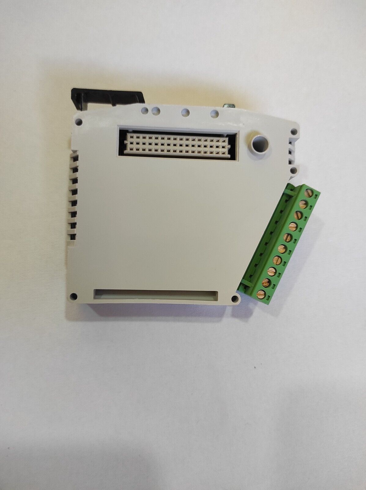
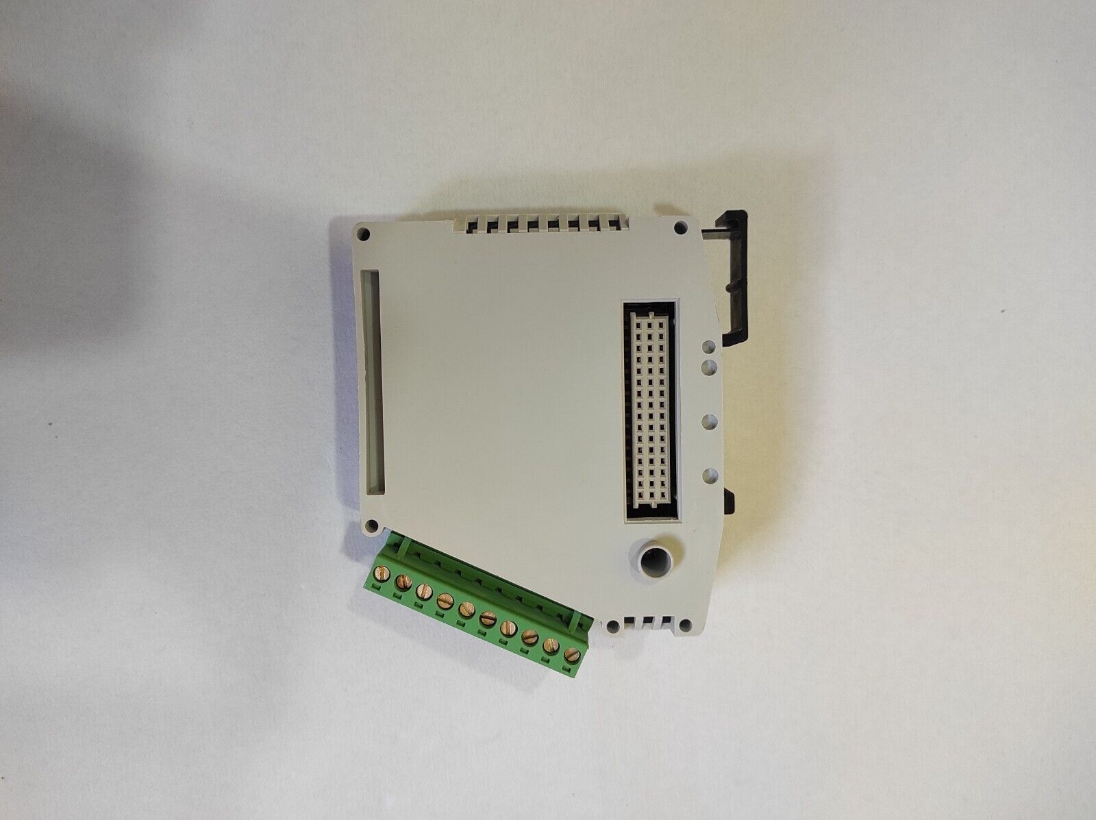
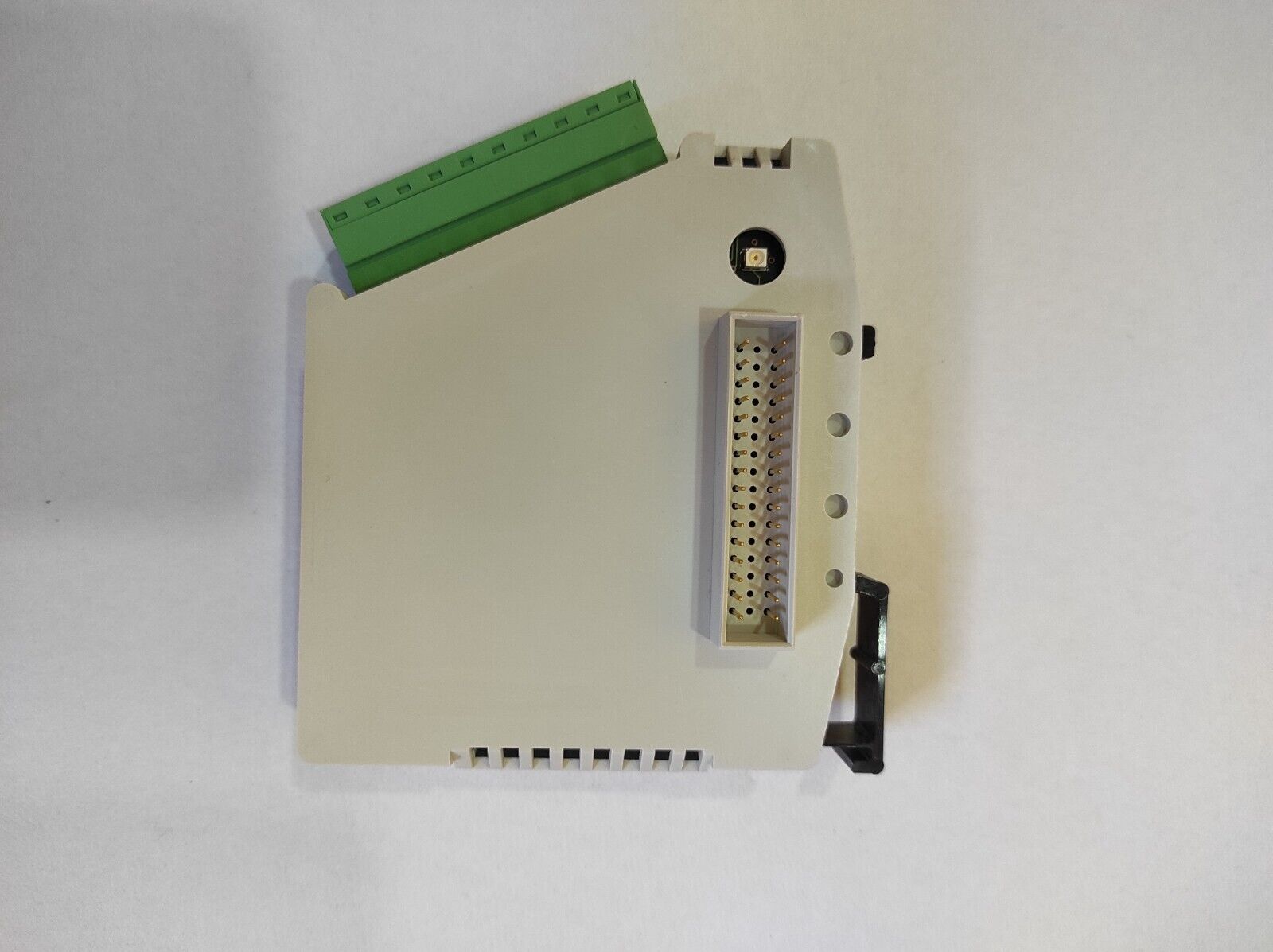
Autronica BSL 325 AUTROLON booster New, FAST SHIP DHL, 1 YEAR Warranty
$ 274.56
- Description
- Size Guide
Description
AUTROLON booster - BSL-325AutroSafe interactive fire detection system
Product datasheet
116-P-BSL-325/CGB, 2009-07-07 Protecting life, environment and property…
Screw
terminal 1
Front view when mounted on rail
Screw
terminal 10
H8 H7 H6 H5 H4 H3 H2 H1
Indicators
Features
Boosts the data signals on the AutroSafe local operating
network; AUTROLON
Ensures reliable communication where larger distances
between panels on the AUTROLON are necessary
Easily plugged onto other I/O modules on a standard
mounting rail inside the Fire alarm control panel/controller
Powered from I/O module stack or screw terminals
Designed to meet EN 54 requirements and conforms to
CE standards
Applications
The AUTROLON booster BSL-325 is used to boost the data
signals on the AutroSafe local operating network;
AUTROLON.
The booster ensures reliable communication in cases where
larger distances between panels are necessary. By using
AUTROLON boosters the total cable length can be greatly
increased (see requirements and limitations below).
If the module is mounted on the standard mounting rail inside
the Fire alarm control panel/controller it is powered with 24
VDC from the I/O module stack. If it is not mounted on the
standard mounting rail, external 24 VDC Power must be
supplied to the screw terminals.
The booster can also be used in cases when different cable
types* (AUTROLON cables) are used in a distributed system.
*NOTE: The use of different cable types is not recommended.
If, however, a mix of different cable types is required, the
cable types can be “isolated” from each other by the use of
the AUTROLON booster. In this way each cable can be
terminated properly and the signal will be amplified before it is
transferred from one cable to the other.
Requirements
In cases when it is necessary to boost the data signals on the
AUTROLON, a minimum of 2 Boosters must be used in one
AUTROLON ring to maintain AUTROLON loop redundancy.
Boosters are required if the AUTROLON cable is more than
1km in length. Boosters must be evenly spread round the
AUTROLON ring.
Limitations
Maximum 1000 metres between any two boosters
Maximum 8 panels between any two boosters
Maximum 6 boosters per AUTROLON ring
Maximum 32 panels per AUTROLON ring
Maximum length 2,8 km (the total AUTROLON ring with
boosters)
Connections/indicators
H1 green LED, LON A transmitter active
H2 green LED, LON B transmitter active
H3 red LED, not used
H4 green LED, module OK when blinking
H5 green LED, > 0,01 % network load
H6 green LED, > 1 % network load
H7 green LED, > 10 % network load
H8 green LED, > 50 % network load
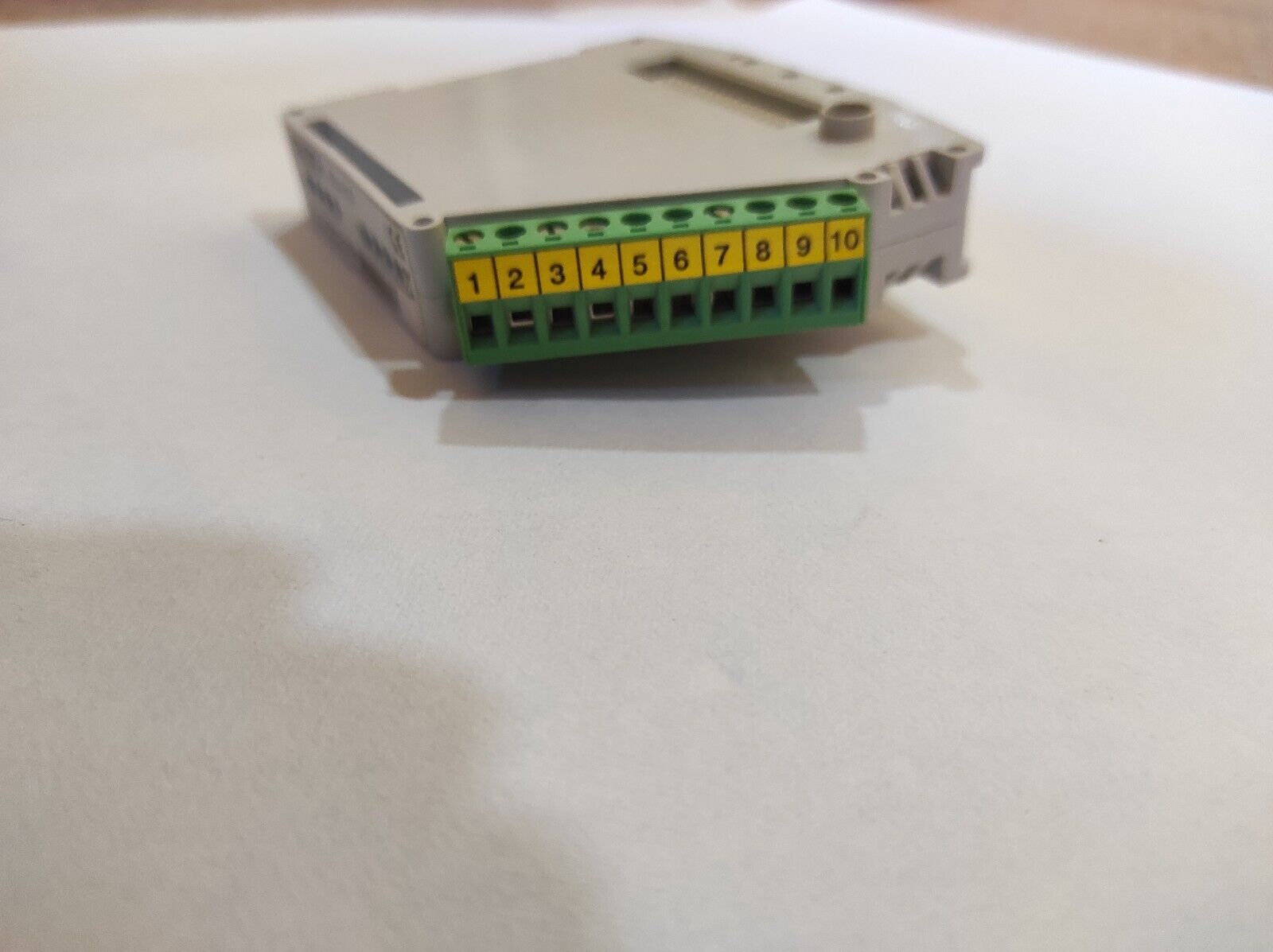
BSL-325 has the following connections:
Screw terminal no. Signal
1 LON A (polarity independent)
2 LON A (polarity independent)
3 Shield LON A
4 LON B (polarity independent)
5 LON B (polarity independent)
6 Shield LON B
7 Do NOT connect
8 Do NOT connect
9 +24 VDC supply
10 0 VDC supply
AUTROLON booster - BSL-325
AUTRONICA FIRE AND SECURITY AS
Technical specifications
Dimensions (mm)
HxDxW
89x105x32
Weight (g) 81
Materials Top and bottom: Zytel FR7200
Snap on mounting device: Zytel 7335S
Mounting Onto a standard 35mm mounting rail
inside the Fire alarm control panel,
Controller or separate box.
Electrical connection Internal system: plug in connection
Screw terminals (maximum cable
dimension 2,5mm2)
Supply voltage 21 - 29 VDC
Internal current
consumption
Maximum 100 mA,
typically 30 mA
Degree of protection IP20
Humidity 93% relative humidity at 40oC
Working temperature -20 to +60oC
Cable specification Twisted pair, 100Ω characteristic
impendance
Part number Description
116-BSL-325 AUTROLON booster
Block diagram – typical example
Maximum 1000 metres between any two boosters
Maximum 8 panels between any two boosters
Maximum 6 boosters per AUTROLON ring
Maximum 32 panels per AUTROLON ring
Maximum length 2,8 km (the total AUTROLON
ring with boosters)
